TP-Link - EAP - Configuring A Standalone Access Point - Advanced Features
Configure the IP Address of the EAP Configure the Wireless Parameters Configure Portal Authentication Configure MAC Filtering Configure Scheduler Configure QoS Configure Rogue AP Detection
This guide applies to:
EAP225-Outdoor 1.0, EAP110-Outdoor 3.0, EAP110 4.0, EAP115 4.0, EAP115-Wall 1.0, EAP225-Wall 2.0, EAP225 3.0, EAP245 3.0, EAP320 2.0, EAP330 2.0.
1 Configure the IP Address of the EAP
The IP address of the EAP can be a dynamic IP address assigned by the DHCP server or a static IP address manually specified by yourself. By default, the EAP gets a dynamic IP address from the DHCP server;. You can also specify a static IP address according to your needs.
To configure the IP address of the EAP, go to the Network page.
Figure 1-1Configuring IP Address
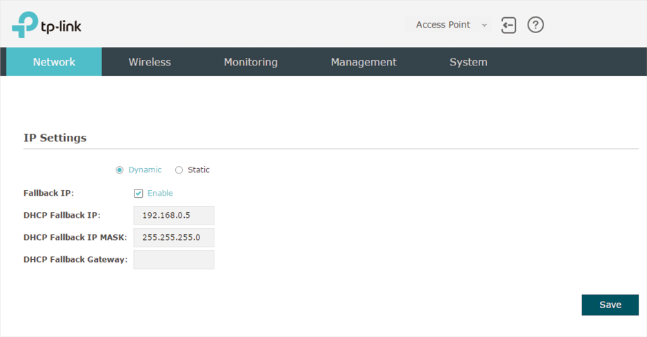
Follow the steps below to configure the IP address of the EAP:
1)Choose your desired IP address mode: Dynamic or Static.
2)Configure the related parameters according to your selection.
Dynamic
If you choose Dynamic as the IP address mode, make sure that there is a reachable DHCP server on your network and the DHCP sever is properly configured to assign IP address and the other network parameters to the EAP.
Figure 1-2Configuring Dynamic IP Address
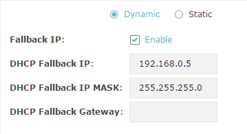
For network stability, you can also configure the fallback IP parameters for the EAP:
|
Fallback IP |
With the fallback IP configured, if the EAP fails to get an IP address from a DHCP server within 10 seconds, the fallback IP will work as the IP address of the EAP. After that, however, the EAP will keep trying to obtain an IP address from the DHCP server until it succeeds. |
|
DHCP Fallback IP |
Specify a fallback IP address for the EAP. Make sure that this IP address is not being used by any other device in the same LAN. |
|
DHCP Fallback IP MASK |
Specify the network mask of the fallback IP. |
|
DHCP Fallback Gateway |
Specify the network gateway. |
Static
If you choose Static as the IP address mode, you need to manually specify an IP address and the related network parameters for the EAP. Make sure that the specified IP address is not being used by any other device in the same LAN.
Figure 1-3Configuring Static IP Address
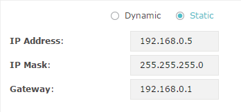
Configure the IP address and network parameters as the following table shows:
|
IP Address |
Specify a static IP address for the EAP. |
|
IP Mask |
Specify the network mask. |
|
Gateway |
Specify the network gateway. |
3)Click Save.
2 Configure the Wireless Parameters
To configure the wireless parameters, go to the Wireless > Wireless Settings page.
Figure 2-1Wireless Settings Page
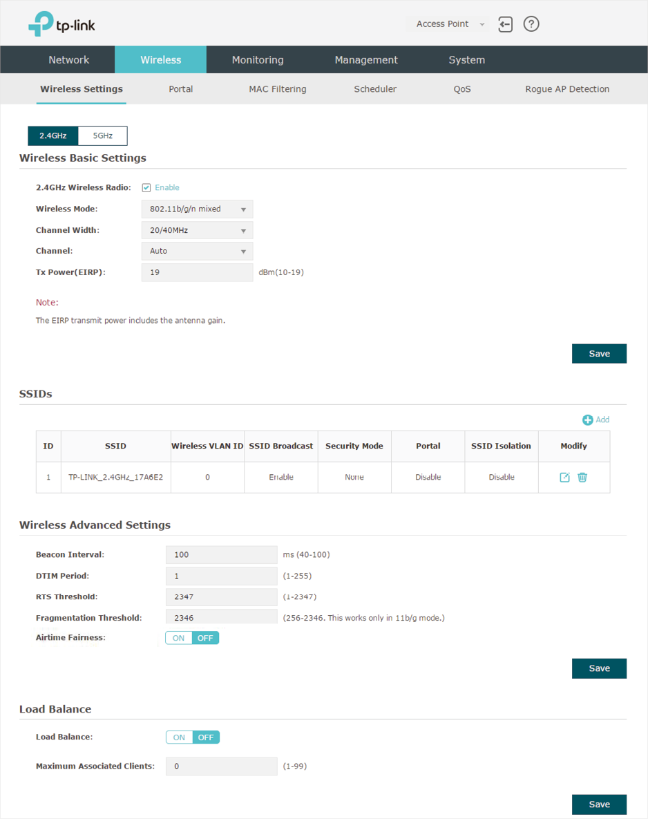
The following sections introduce these contents: Configure Basic Wireless Settings, Configure SSIDs, Configure Wireless Advanced Settings and Configure Load Balance.
|
|
Note: •For a dual-band EAP, there are two bands: 2.4GHz and 5GHz. The wireless parameters are separately set on each band. You can click •The following figures take 2.4GHz as an example. |
2.1Configure Basic Wireless Settings
Proper wireless parameters can improve the quality of your wireless network. This section introduces how to configure the basic wireless parameters.
Figure 2-2Configuring Basic Wireless Settings
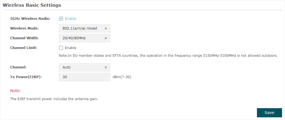
Follow the steps below to complete the basic wireless settings:
1)If your EAP is a dual-band device, click  to choose a frequency band to be configured.
2)In the Wireless Basic Settings section, configure the following parameters:
|
2.4GHz Wireless Radio/5GHz Wireless Radio |
Check the box to enable 2.4GHz/5GHz Wireless Radio. By default, it is enabled. Only when this option is enabled will the wireless radio on 2.4GHz/5GHz band works. |
|
Wireless Mode |
Select the protocol standard for the wireless network. For 2.4GHz network, we recommend that you select 802.11b/g/n. In this way, clients supporting any one of these modes can access your wireless network. For 5GHz network, we recommend that you select 802.11n/ac or 802.11a/n/ac. In this way, clients supporting any one of these modes can access your wireless network. |
|
Channel Width |
Select the channel width. According to IEEE 802.11n standard, using a higher bandwidth can increase wireless throughput. However, you may choose a lower bandwidth due to the following reasons: To increase the available number of channels within the limited total bandwidth. To avoid interference from overlapping channels occupied by other devices in the environment. Lower bandwidth can concentrate higher transmit power, increasing stability of wireless links over long distances. |
|
Channel Limit |
Check the box to enable the Channel Limit function. With this function enabled, the wireless frequency 5150MHz~5350MHz will be disabled. This function can influence the available options in Channel. This feature is only available for 5GHz wireless configuration of EAP225-Outdoor. |
|
Channel |
Select the channel used by the EAP. For example, 1/2412MHz means that the channel is 1 and the frequency is 2412MHz. By default, the channel is automatically selected, and we recommend that you keep the default setting. |
|
Tx Power (EIRP) |
Specify the transmit power value. If this value is set to be larger than the maximum transmit power that is allowed by the local regulation, the regulated maximum transmit power will be applied in the actual situation. Note: In most cases, it is unnecessary to use the maximum transmit power. Specifying a larger transmit power than needed may cause interference to the neighborhood. Also it consumes more power and reduces longevity of the device. |
3)Click Save.
2.2 Configure SSIDs
SSID (Service Set Identifier) is used as an identifier for a wireless LAN, and is commonly called as the “network name“. Clients can find and access the wireless network through the SSID. For one EAP, you can build up to eight SSIDs per frequency band.
Figure 2-3 Configuring SSID
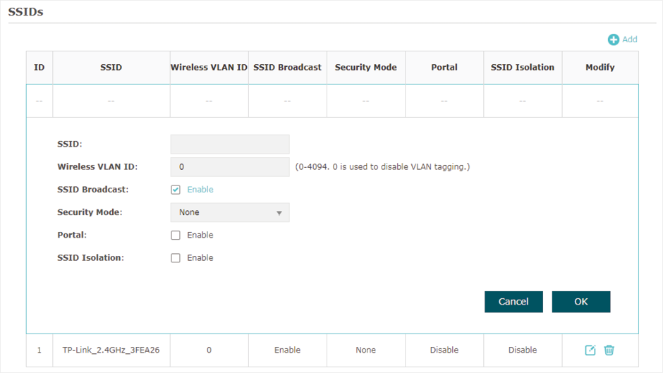
Follow the steps below to create an SSID on the EAP:
1)If your EAP is a dual-band device, click  to choose a frequency band on which the new SSID will be created.
2)Click  to add a new SSID on the chosen band.
|
|
Note: If there are SSIDs already in the list, you can also click |
3)Configure the following required parameters for this SSID:
|
SSID |
Specify a name for the wireless network. |
|
Wireless VLAN ID |
Set a VLAN ID for the wireless network. It supports maximum 8 VLANs per frequency band. With this feature, the EAP can work together with the switches supporting 802.1Q VLAN. The EAP adds different VLAN tags to the clients which are connected to the corresponding wireless network. The clients in different VLANs cannot directly communicate with each other. VLAN 0 means that the EAP does not add any VLAN tag to the clients which are connected to this wireless network. Note: Clients connected to the EAP via Ethernet cable do not belong to any VLAN. Thus wired client can communicate with all the wireless clients despite the VLAN settings. |
|
SSID Broadcast |
With the option enabled, EAP will broadcast the SSID to the nearby hosts, so that those hosts can find the wireless network identified by this SSID. If this option is disabled, users must enter the SSID manually to connect to the EAP. |
|
Security Mode |
Select the security mode of the wireless network. There are four options: None: Clients can access the wireless network without authentication. WEP/WPA-Enterprise/WPA-PSK: Clients need to pass the authentication before accessing the wireless network. For network security, we recommend that you encrypt your wireless network. The following sections will introduce how to configure these security modes. |
|
Portal |
With this option enabled, the Portal configuration will be applied to this wireless network. Portal provides authentication service for the clients who just need temporary access to the wireless network, such as the customers in a shopping mall or in a restaurant. Portal also provides a way for vendors and companies to put their advertisements on the authentication page. |
|
SSID Isolation |
With this option enabled, the devices connected to the same SSID cannot communicate with each other. |
4)Click OK to create the SSID.
Following is the detailed instructions about how to configure WEP, WPA-Enterprise and WPA-PSK.
WEP
WEP (Wired Equivalent Privacy) is a traditional encryption method. It has been proved that WEP has security flaws and can easily be cracked, so WEP cannot provide effective protection for wireless networks. Since WPA-PSK and WPA-Enterprise are much safer than WEP, we recommend that you choose WPA-PSK or WPA-Enterprise if your clients also support them.
|
|
Note: WEP is not supported in 802.11n mode or 802.11ac mode. If WEP is applied in 802.11n, 802.11 ac or 802.11n/ac mixed mode, the clients may not be able to access the wireless network. If WEP is applied in 802.11b/g/n mode (2.4GHz) or 802.11a/n (5GHz), the EAP may work at a low transmission rate. |
Figure 2-4WEP
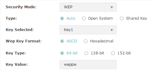
The following table detailedly introduces how to configure each item:
|
Type |
Select the authentication type for WEP. Auto: The EAP can select Open System or Shared Key automatically based on the wireless capability and request of the clients. Open System: Clients can pass the authentication and associate with the wireless network without password. However, correct password is necessary for data transmission. Shared Key: Clients have to input the correct password to pass the authentication, otherwise the clients cannot associate with the wireless network or transmit data. |
|
Key Selected |
Select one key to specify. You can configure four keys at most. |
|
WEP Key Format |
Select ASCII or Hexadecimal as the WEP key format. ASCII: With this format selected, the WEP key can be any combination of keyboard characters of the specified length. Hexadecimal: With this format selected, the WEP key can be any combination of hexadecimal digits (0-9, a-f, A-F) with the specified length. |
|
Key Type |
Select the WEP key length for encryption. 64Bit: Enter 10 hexadecimal digits or 5 ASCII characters. 128Bit: Enter 26 hexadecimal digits or 13 ASCII characters. 152Bit: Enter 32 hexadecimal digits or 16 ASCII characters. |
|
Key Value |
Enter the WEP keys. The length and valid characters are determined by the key format and key type. |
WPA-Enterprise
WPA-Enterprise (Wi-Fi Protected Access-Enterprise) is a safer encryption method compared with WEP and WAP-PSK. It requires a RADIUS server to authenticate the clients via 802.1X and EAP (Extensible Authentication Protocol). WPA-Enterprise can generate different passwords for different clients, which ensures higher network security. But it also costs more to maintain the network, so it is more suitable for business networks.
Figure 2-5WPA-Enterprise
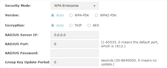
The following table introduces how to configure each item:
|
Version |
Select the version of WPA-Enterprise. Auto: The EAP will automatically choose the version used by each client device. WPA/WPA2: They’re two versions of WPA security mode. WPA2 is an update of WPA. Compared with WPA, WPA2 introduces AES algorithm and CCMP encryption. Theoretically, WPA2 is securer than WPA. |
|
Encryption |
Select the Encryption type. Auto: The default setting is Auto and the EAP will select TKIP or AES automatically based on the client device’s request. TKIP: Temporal Key Integrity Protocol. TKIP is not supported in 802.11n mode, 802.11ac mode or 802.11n/ac mixed mode. If TKIP is applied in 802.11n, 802.11 ac or 802.11n/ac mixed mode, the clients may not be able to access the wireless network. If TKIP is applied in 11b/g/n mode (2.4GHz) or 11a/n mode(5GHz), the device may work at a low transmission rate. AES: Advanced Encryption Standard. It is securer than TKIP. |
|
RADIUS Server IP |
Enter the IP address of the Radius Server. |
|
RADIUS Port |
Enter the port number of the Radius Server. |
|
RADIUS Password |
Enter the shared secret key of the Radius server. |
|
Group Key Update Period |
Specify an update period of the encryption key. The update period instructs how often the EAP should change the encryption key. 0 means that the encryption key does not change at anytime. |
WPA-PSK
WPA-PSK (Wi-Fi Protected Access-PSK) is based on a pre-shared key. It is characterized by high safety and simple settings, so it is mostly used by common households and small businesses.
Figure 2-6WPA-PSK

The following table introduces how to configure each item:
|
Version |
Select the version of WPA-Enterprise. Auto: The EAP will automatically choose the version used by each client device. WPA-PSK/WPA2-PSK: They’re two versions of WPA-PSK security mode. WPA2-PSK is an update of WPA-PSK. Compared with WPA, Theoretically, WPA2 is securer than WPA. |
|
Encryption |
Select the Encryption type. Auto: The default setting is Auto and the EAP will select TKIP or AES automatically based on the client device’s request. TKIP: Temporal Key Integrity Protocol. TKIP is not supported in 802.11n mode, 802.11ac mode or 802.11n/ac mixed mode. If TKIP is applied in 802.11n, 802.11 ac or 802.11n/ac mixed mode, the clients may not be able to access the wireless network. If TKIP is applied in 11b/g/n mode (2.4GHz) or 11a/n mode(5GHz), the device may work at a low transmission rate. AES: Advanced Encryption Standard. It is securer than TKIP. |
|
Wireless Password |
Configure the wireless password with ASCII or Hexadecimal characters. For ASCII, the length should be between 8 and 63 and the valid characters contain numbers, letters (case-sensitive) and common punctuations. For Hexadecimal, the length should be between 8 and 64, and the valid characters contain: 0-9, a-f, A-F. |
|
Group Key Update Period |
Specify an update period of the encryption key. The update period instructs how often the EAP should change the encryption key. 0 means that the encryption key does not change at anytime. |
2.3 Configure Wireless Advanced Settings
Configure the advanced wireless parameters of the EAP and click Save.
Figure 2-7Wireless Advanced Settings

The following table introduces how to configure each item:
|
Beacon Interval |
Beacons are transmitted periodically by the EAP device to announce the presence of a wireless network for the clients. Beacon Interval determines the time interval of the beacons sent by the EAP device. You can specify a value between 40 and 100ms. The default is 100ms. |
|
DTIM Period |
The DTIM (Delivery Traffic Indication Message) is contained in some Beacon frames. It indicates whether the EAP device has buffered data for client devices. The DTIM Period indicates how often the clients served by this EAP device should check for buffered data still on the EAP device awaiting pickup. You can specify the value between 1-255 Beacon Intervals. The default value is 1, indicating that clients check for buffered data at every beacon. An excessive DTIM interval may reduce the performance of multicast applications, so we recommend you keep the default value. |
|
RTS Threshold |
RTS/CTS (Request to Send/Clear to Send) is used to improve the data transmission efficiency of the network with hidden nodes, especially when there are lots of large packets to be transmitted. When the size of a data packet is larger than the RTS Threshold, the RTS/CTS mechanism will be activated. With this mechanism activated, before sending a data packet, the client will send an RTS packet to the EAP to request data transmitting. And then the EAP will send CTS packet to inform other clients to delay their data transmitting. In this way, packet collisions can be avoided. For a busy network with hidden nodes, a low threshold value will help reduce interference and packet collisions. But for a not-so-busy network, a too low threshold value will cause bandwidth wasting and reduce the data throughput. The recommended and default value is 2347 bytes. |
|
Fragmentation Threshold |
The fragmentation function can limit the size of packets transmitted over the network. If the size of a packet exceeds the Fragmentation Threshold, the fragmentation function is activated and the packet will be fragmented into several packets. Fragmentation helps improve network performance if properly configured. However, a too low fragmentation threshold may result in poor wireless performance caused by the extra work of dividing up and reassembling of frames and increased message traffic. The recommended and default value is 2346 bytes. |
|
Airtime Fairness |
EAP225_V3, EAP225-Outdoor_V1, EAP245_V3, EAP320 and EAP330 support this feature. With this option enabled, each client connected to the EAP can get the same amount of time to transmit data, avoiding low-data-rate clients to occupy too much network bandwidth. Compared with the relatively new client devices, some legacy client devices support slower wireless rate. If they communicate with the same EAP, the slower clients take more time to transmit and receive data compared with the faster clients. As a result, the overall wireless throughput of the network decreases. So under such circumstance, we recommend that you enable this feature to ensure the data transmission time for the faster clients. In this way, the network overall throughput can be improved. For EAP225_V3 and EAP225-Outdoor_V1, with this option enabled, 50 wireless clients can connect to the EAP at most in 2.4GHz band. |
2.4 Configure Load Balance
With the Load Balance feature, you can limit the maximum number of clients who can access the EAP. In this way, you can achieve rational use of network resources.
Figure 2-8Load Balance

Follow the steps below to configure Load Balance:
1)Click  to choose a frequency band on which the load balance feature will take effect.
2)In the Load Balance section, click  to enable this feature. The ON button with cyan background color indicates this feature is enabled.
3)Specify the maximum number of clients who can connect to the EAP at the same time. While the number of connected clients has reached the limit and there are more clients requesting to access the network, the EAP will disconnect those with weaker signals.
4)Click Save.
3 Configure Portal Authentication
Portal authentication provides authentication service to the clients that only need temporary access to the wireless network, such as the customers in a restaurant or in a supermarket. To access the network, these clients need to enter the authentication login page and use the correct login information to pass the authentication. In addition, you can customize the authentication login page and specify a URL which the authenticated clients will be redirected to.
In this module, you can also configure Free Authentication Policy, which allows the specific clients to access the specific network resources without authentication.
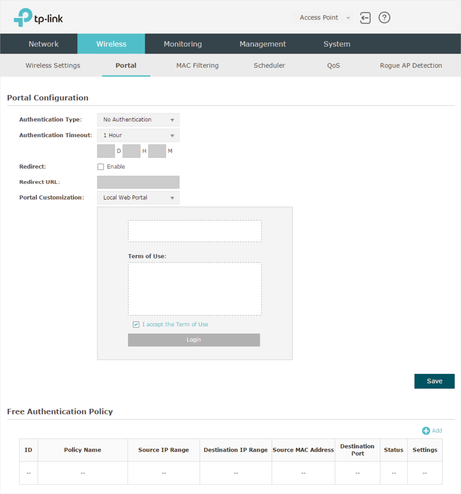
To configure portal authentication, go to the Wireless > Portal page.
Figure 3-1 Portal Page
3.1 Configure Portal
Three portal authentication types are available: No Authentication, Local Password and External Radius Server. The following sections introduce how to configure each authentication type.
No Authentication
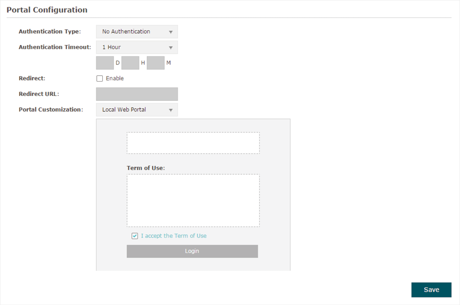
With this authentication type configured, clients can pass the authentication and access the network without providing any login information. They only need to accept the term of use on the authentication page.
Figure 3-2 Portal-No Authentication
Follow the steps below to configure No Authentication as the portal authentication type:
1)Select No Authentication as the authentication type.
2)Configure the relevant parameters as the following table shows:
|
Authentication Timeout |
Specify the value of authentication timeout. A client’s authentication will expire after the authentication timeout and the client needs to log in to the authentication page again to access the network. Options include 1 Hour, 8 Hours, 24 Hours, 7 Days, and Custom. With Custom selected, you can customize the time in days, hours, and minutes. |
|
Redirect |
With this function configured, the newly authenticated client will be redirected to the specific URL. |
|
Redirect URL |
With Redirect enabled, you also need to enter the URL in this field. The newly authenticated client will be redirected to this URL. |
|
Portal Customization |
Configure the authentication page. Local Web Portal is the only available option in this authentication type. Enter the title and term of use in the two boxes. The EAP uses its built-in web server to provide this authentication page for clients. To pass the authentication, clients only need to check the box of I accept the Term of Use and click the Login button. |
3)Click Save.
4)Go to the Wireless > Wireless Settings page and enable the Portal option for the specific SSID. Then the portal authentication feature will take effect on this SSID.
Figure 3-3 Enabling Portal

Local Password
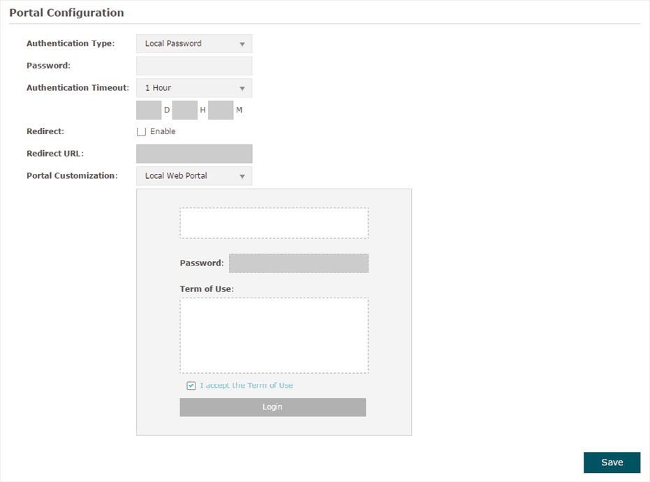
With this authentication type configured, clients are required to provide the correct password to pass the authentication.
Figure 3-4Portal-Local Password
Follow the steps below to configure Local Password as the portal authentication type:
1)Select Local Password as the authentication type.
2)Configure the relevant parameters as the following table shows:
|
Authentication Timeout |
Specify the value of authentication timeout. A client’s authentication will expire after the authentication timeout and the client needs to log in to the authentication page again to access the network. Options include 1 Hour, 8 Hours, 24 Hours, 7 Days, and Custom. With Custom selected, you can customize the time in days, hours, and minutes. |
|
Password |
Specify a password for authentication. |
|
Redirect |
With this function configured, the newly authenticated client will be redirected to the specific URL. |
|
Redirect URL |
With Redirect enabled, you also need to enter the URL in this field. The newly authenticated client will be redirected to this URL. |
|
Portal Customization |
Configure the authentication page. Local Web Portal is the only available option is this authentication type. Enter the title and term of use in the two boxes. The EAP uses its built-in web server to provide this authentication page for clients. To pass the authentication, clients need to provide the correct password in the Password field, check the box of I accept the Term of Use and click the Login button. |
3)Click Save.
4)Go to the Wireless > Wireless Settings page and enable the Portal option for the specific SSID. Then the portal authentication feature will take effect on this SSID.
Figure 3-5Enabling Portal

External Radius Server
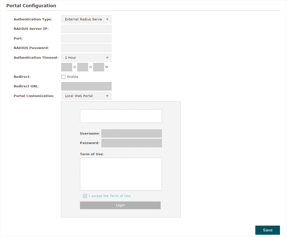
If you have a RADIUS server on the network to authenticate the clients, you can select External Radius Server. Clients need to provide the correct login information to pass the authentication.
Figure 3-6Portal-External RADIUS Server
Follow the steps below to configure External Radius Server as the portal authentication type:
1)Build a Radius server on the network and make sure that it is reachable by the EAP.
2)Go to the Portal configuration page on the EAP. Select External Radius Server as the authentication type.
3)Configure the relevant parameters as the following table shows:
|
RADIUS Server IP |
Enter the IP address of RADIUS server. |
|
Port |
Enter the port of the RADIUS server. |
|
RADIUS Password |
Enter the password of the RADIUS server. |
|
Authentication Timeout |
Specify the value of authentication timeout. A client’s authentication will expire after the authentication timeout and the client needs to log in to the authentication page again to access the network. Options include 1 Hour, 8 Hours, 24 Hours, 7 Days, and Custom. With Custom selected, you can customize the time in days, hours, and minutes. |
|
Redirect |
With this function configured, the newly authenticated client will be redirected to the specific URL. |
|
Redirect URL |
With Redirect enabled, you also need to enter the URL in this field. The newly authenticated client will be redirected to this URL. |
|
Portal Customization |
Configure the authentication page. There are two options: Local Web Portal and External Web Portal. Local Web Portal Enter the title and term of use in the two boxes. The EAP uses its built-in web server to provide this authentication page for clients. To pass the authentication, clients need to provide the correct username and password in the Username and Password fields, check the box of I accept the Term of Use and click the Login button. External Web Portal With External Web Portal configured, the authentication page will be provided by the web portal server built on the network. To configure External Web Portal, you need to complete the following configurations: 1. Build an external web portal server on your network and make sure that it is reachable by the EAP. 2. On this configuration page, enter the URL of the authentication page provided by the external portal server.
3. Add the external web portal server to the Free Authentication Policy list. In this way, clients can access the web portal server before authenticated. For details about how to configure |
4)Click Save.
5)Go to the Wireless > Wireless Settings page and enable the Portal option for the specific SSID. Then the portal authentication feature will take effect on this SSID.
Figure 3-7Enabling Portal

3.2 Configure Free Authentication Policy
Free Authentication Policy allows some specific clients to access the specific network resources without authentication. For example, you can set a free authentication policy to allow clients to visit the external web portal server before authenticated. In this way, the clients can visit the login page provided by the web portal server and then pass the subsequent authentication process.
Figure 3-8Free Authentication Policy

Follow the steps below to add free authentication policy.
1)In the Free Authentication Policy section, click  to load the following page.
Figure 3-9Adding Policy
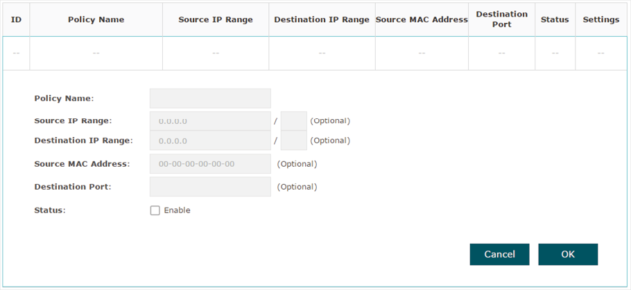
2)Configure the following parameters. When all the configured conditions are met, the client can access the network without authentication.
|
Policy Name |
Specify a name for the policy. |
|
Source IP Range |
Specify an IP range with the subnet and mask length. The clients in this IP range can access the network without authentication. Leaving the field empty means that clients with any IP address can access the specific resources. |
|
Destination IP Range |
Specify an IP range with the subnet and mask length. The devices in this IP range can be accessed by the clients without authentication. Leaving the field empty means that all devices in the LAN can be accessed by the specific clients. |
|
Source MAC Address |
Specify the MAC address of the client, who can access the specific resources without authentication. Leaving the field empty means that clients with any MAC address can access the specific resources. |
|
Destination Port |
Specify the port number of the service. When using this service, the clients can access the specific resources without authentication. Leaving the field empty means that clients can access the specific resources no matter what service they are using. |
|
Status |
Check the box to enable the policy. |
|
|
Tips When External Web Portal is configured in the portal configuration, you should set the IP address and subnet mask of the external web server as the Destination IP Range. As for Source IP Range, Source MAC Address and Destination Port, you can simply keep them as empty or configure them according to your actual needs. |
3. Click OK to add the policy.
4 Configure MAC Filtering
MAC Filtering is used to allow or block the clients with specific MAC addresses to access the network. With this feature you can effectively control clients’ access to the wireless network according to your needs.
To configure MAC Filtering, go to the Wireless > MAC Filtering page.
Figure 4-1MAC Filtering
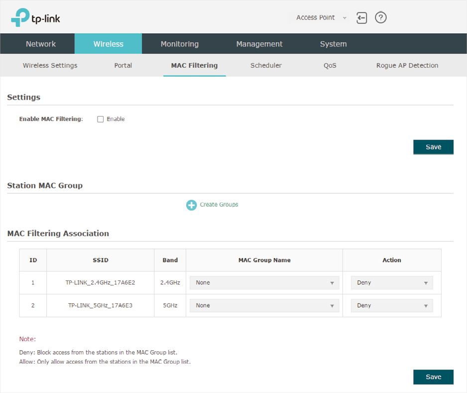
Follow the steps below to configure MAC Filtering on this page:
1)In the Settings section, check the box to enable MAC Filtering, and click Save.
Figure 4-2Enabling MAC Filtering

2)In the Station MAC Group section, click  and the following page will appear.
Figure 4-3Creating Groups

Click  and specify a name for the MAC group to be created. Click OK. You can create up to eight MAC groups.
Figure 4-4Creating Group
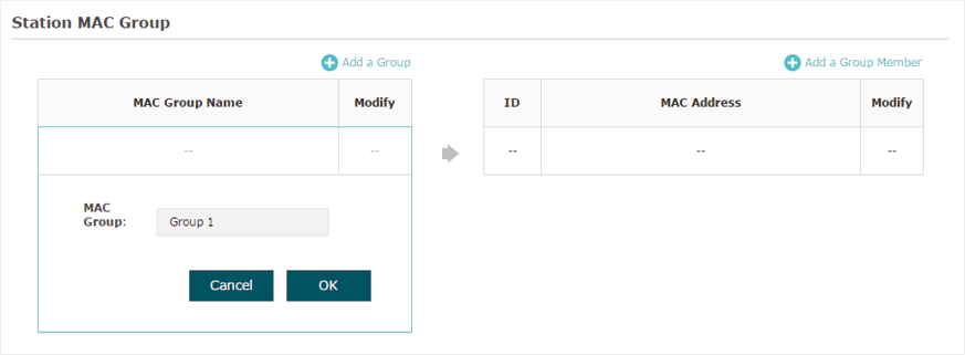
Select a MAC group in the group list (the color of the selected one will change to blue). Click  to add group members to the MAC group. Specify the MAC address of the host and click OK. In the same way, you can add more MAC addresses to the selected MAC group.
Figure 4-5Adding Group Member
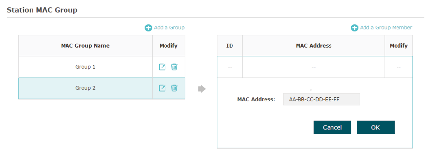
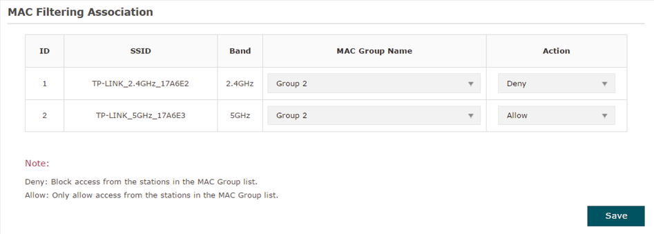
3)In the MAC Filtering Association section, configure the filtering rule. For each SSID, you can select a MAC group in the MAC Group Name column and select the filtering rule (Allow/Deny) in the Action column. Click Save.
For example, the following configuration means that the hosts in Group 2 are denied to access the SSID TP-LINK_2.4GHz_17A6E2 on the 2.4GHz band and allowed to access the SSID TP-LINK_5GHz_17A6E3 on the 5GHz band.
Figure 4-6 MAC Filtering Example
5 Configure Scheduler
With the Scheduler feature, the EAP or its wireless network can automatically turn on or off at the time you set. For example, you can schedule the radio to operate only during the office working time to reduce power consumption.
To configure Scheduler, go to the Wireless > Scheduler page.
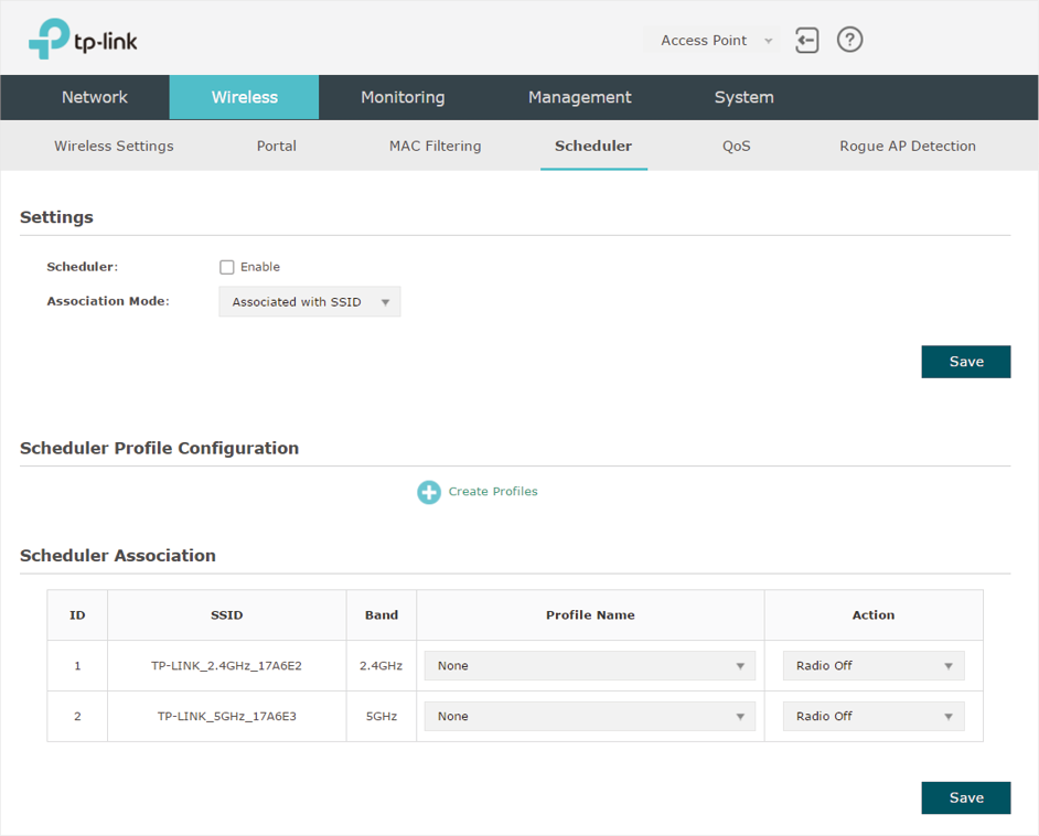
Figure 5-1Scheduler Page
Follow the steps below to configure Scheduler on this page:
1)In the Settings section, check the box to enable Scheduler and select the Association Mode. There are two modes: Associated with SSID (the scheduler profile will be applied to the specific SSID) and Associated with AP (the profile will be applied to all SSIDs on the EAP). Then click Save.
Figure 5-2Enabling Scheduler

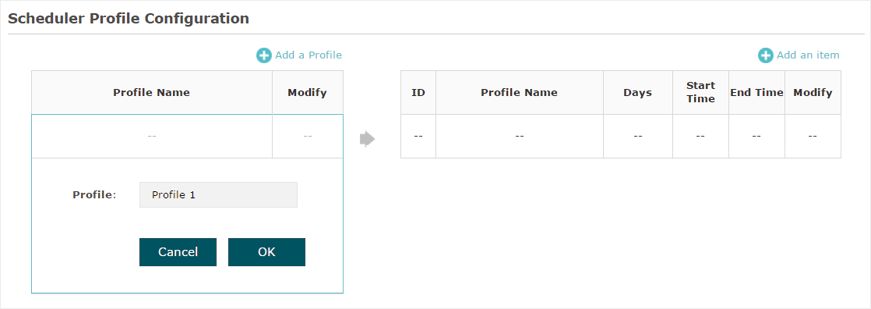
2)In the Scheduler Profile Configuration section, click  and the following page will appear.
Figure 5-3Creating Profile

Click  and specify a name for the profile to be created. Click OK. You can create up to eight profiles.
Figure 5-4Specifying Name for Profile
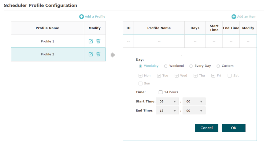
Select a profile in the list (the color of the selected one will change to blue). Click  to add time range items to the profile. Specify the Day, Start Time and End Time of the time range, and click OK.
Figure 5-5Adding Item
|
|
Tips You can add up to eight time range items for one profile. If there are several time range items in one profile, the time range of this profile is the sum of all of these time ranges. |
3)In the Scheduler Association section, configure the scheduler rule. There are two association modes: Association with SSID and Association with AP. The following sections introduce how to configure each mode.
Association with SSID
If you select Association with SSID in step 1, the Scheduler Association table will display all the SSIDs on the EAP. For each SSID, you can select a profile in the Profile Name column and select the scheduler rule (Radio On/Radio Off) in the Action column. Then click Save.
For example, the following configuration means that during the time range defined in Profile2, the radio of SSID TP-LINK_2.4GHZ_17A6E2 is on and the radio of SSID TPLINK_5GHz_17A6E3 is off.
Figure 5-6Association With SSID

Association with AP
If you select Association with AP in step 1, the Scheduler Association table will display the name and MAC address of the EAP. Select a profile in the Profile Name column and select the scheduler rule (Radio On/Radio Off) in the Action column. Then click Save.
For example, the following configuration means that during the time range defined in Profile2, the radio of all SSIDs on the EAP is on.
Figure 5-7Association With AP

6 Configure QoS
Quality of service (QoS) is used to optimize the throughput and performance of the EAP when handling differentiated wireless traffic, such as Voice-over-IP (VoIP), other types of audio, video, streaming media, and traditional IP data.
In QoS configuration, you should set parameters on the transmission queues for different types of wireless traffic and specify minimum and maximum wait time for data transmission. In normal use, we recommend that you keep the default values.
To configure QoS, go to the Wireless > QoS page.
Figure 6-1QoS Page
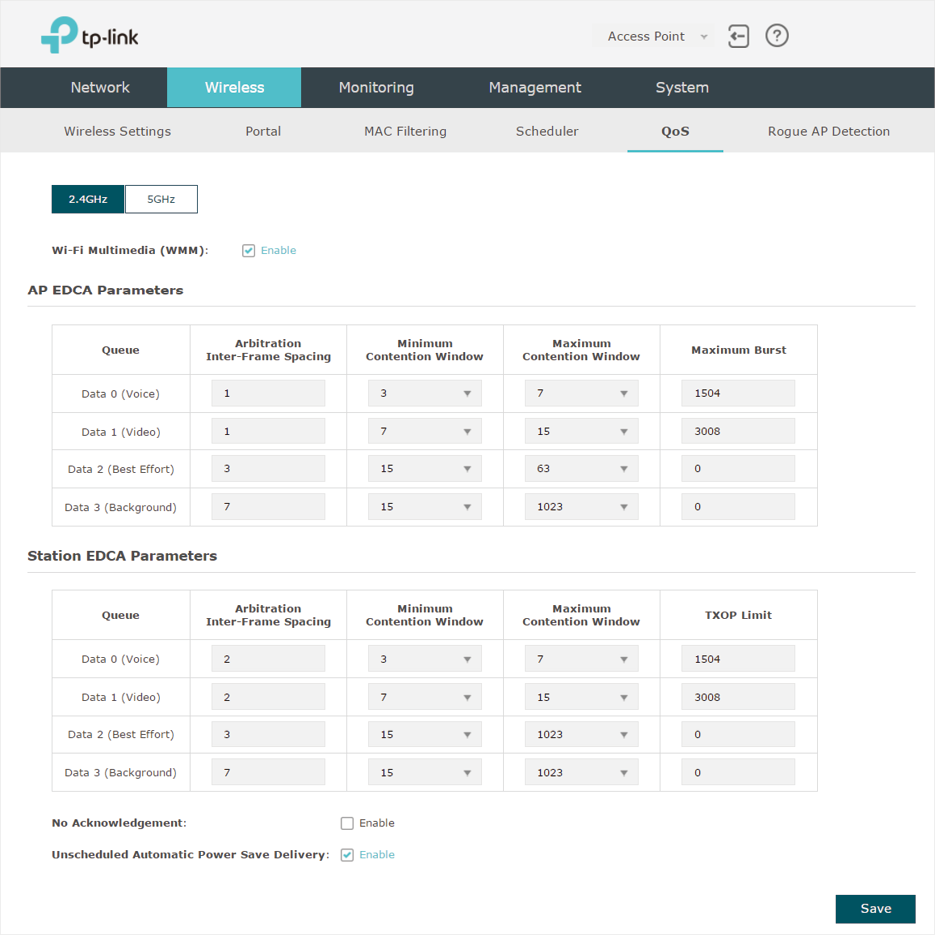
Follow the steps below to configure QoS on this page:
1)Click  to choose a frequency band to be configured.
2)Check the box to enable Wi-Fi Multimedia (WMM). With WMM enabled, the EAP uses the QoS function to guarantee the high priority of the transmission of audio and video packets.
Figure 6-2WMM

|
|
Tips If 802.11n only mode is selected in 2.4GHz (or 802.11n only, 802.11ac only, or 802.11 n/ac mixed mode selected in 5GHz), the WMM should be enabled. If WMM is disabled, the 802.11n only mode cannot be selected in 2.4GHz (or 802.11n only, 802.11ac only, or 802.11 n/ac mixed mode in 5GHz). |
3)In the AP EDCA Parameters section, configure the AP EDCA ((Enhanced Distributed Channel Access) parameters. AP EDCA parameters affect traffic flowing from the EAP device to the client station. The following table detailedly explains these parameters.
Figure 6-3AP EDCA Parameters

The following table detailedly explains these parameters:
|
Queue |
Displays the transmission queue. By default, the priority from high to low is Data 0, Data 1, Data 2, and Data 3. The priority may be changed if you reset the EDCA parameters. Data 0 (Voice): Highest priority queue, minimum delay. Timesensitive data such as VoIP and streaming media are automatically sent to this queue. Data 1 (Video): High priority queue, minimum delay. Time-sensitive video data is automatically sent to this queue. Data 2 (Best Effort): Medium priority queue, medium throughput and delay. Most traditional IP data is sent to this queue. Data 3 (Background): Lowest priority queue, high throughput. Bulk data that requires maximum throughput and is not time-sensitive is sent to this queue (FTP data, for example). |
|
Arbitration Inter- Frame Space |
A wait time for data frames. The wait time is measured in slots. Valid values are from 0 to 15. |
|
Minimum Contention Window |
A list to the algorithm that determines the initial random backoff wait time (window) for retry of a transmission. This value cannot be higher than the value of Maximum Contention Window. |
|
Maximum Contention Window |
The upper limit (in milliseconds) for the doubling of the random backoff value. This doubling continues until either the data frame is sent or the Maximum Contention Window size is reached. This value must be higher than the value of Minimum Contention Window. |
|
Maximum Burst |
Maximum Burst specifies the maximum burst length allowed for packet bursts on the wireless network. A packet burst is a collection of multiple frames transmitted without header information. The decreased overhead results in higher throughput and better performance. |
4)In the Station EDCA Parameters section, configure the station EDCA (Enhanced Distributed Channel Access) parameters. Station EDCA parameters affect traffic flowing from the client station to the EAP device.
Figure 6-4Station EDCA Parameters

The following table detailedly explains these parameters:
|
Queue |
Displays the transmission queue. By default, the priority from high to low is Data 0, Data 1, Data 2, and Data 3. The priority may be changed if you reset the EDCA parameters. Data 0 (Voice): Highest priority queue, minimum delay. Timesensitive data such as VoIP and streaming media are automatically sent to this queue. Data 1 (Video): High priority queue, minimum delay. Time-sensitive video data is automatically sent to this queue. Data 2 (Best Effort): Medium priority queue, medium throughput and delay. Most traditional IP data is sent to this queue. Data 3 (Background): Lowest priority queue, high throughput. Bulk data that requires maximum throughput and is not time-sensitive is sent to this queue (FTP data, for example). |
|
Arbitration Inter- Frame Space |
A wait time for data frames. The wait time is measured in slots. Valid values are from 0 to 15. |
|
Minimum Contention Window |
A list to the algorithm that determines the initial random backoff wait time (window) for retry of a transmission. This value cannot be higher than the value of Maximum Contention Window. |
|
Maximum Contention Window |
The upper limit (in milliseconds) for the doubling of the random backoff value. This doubling continues until either the data frame is sent or the Maximum Contention Window size is reached. This value must be higher than the value of Minimum Contention Window. |
|
TXOP Limit |
The TXOP Limit is a station EDCA parameter and only applies to traffic flowing from the client station to the EAP device. The Transmission Opportunity (TXOP) is an interval of time, in milliseconds, when a WME (Wireless Multimedia Extensions) client station has the right to initiate transmissions onto the wireless medium (WM) towards the EAP device. The valid values are multiples of 32 between 0 and 8192. |
5)Choose whether to enable the following two options according to your need.
Figure 6-5Configuring More Options

The following table detailedly explains these options:
|
No Acknowledgement |
With this option enabled, the EAP would not acknowledge frames with QosNoAck. No Acknowledgement is recommended if VoIP phones access the network through the EAP device. |
|
Unscheduled Automatic Power Save Delivery |
As a power management method, it can greatly improve the energy-saving capacity of clients. |
6)Click Save.
7 Configure Rogue AP Detection
A Rogue AP is an access point that is installed on a secure network without explicit authorization from the network administrator. With Rogue AP Detection, the EAP can scan all channels to detect the nearby APs and display the detected APs in the Detected Rogue AP list. If the specific AP is known as safe, you can move it to the Trusted APs list. Also, you can backup and import the Trusted AP list as needed.
|
|
Tips The Rogue AP Detection feature is only used for collecting information of the nearby wireless network and does not impact the detected APs, no matter what operations you have executed in this feature. |
To configure Rogue AP Detection, go to the Wireless > Rogue AP Detection page.
Figure 7-1Rogue AP Detection Page
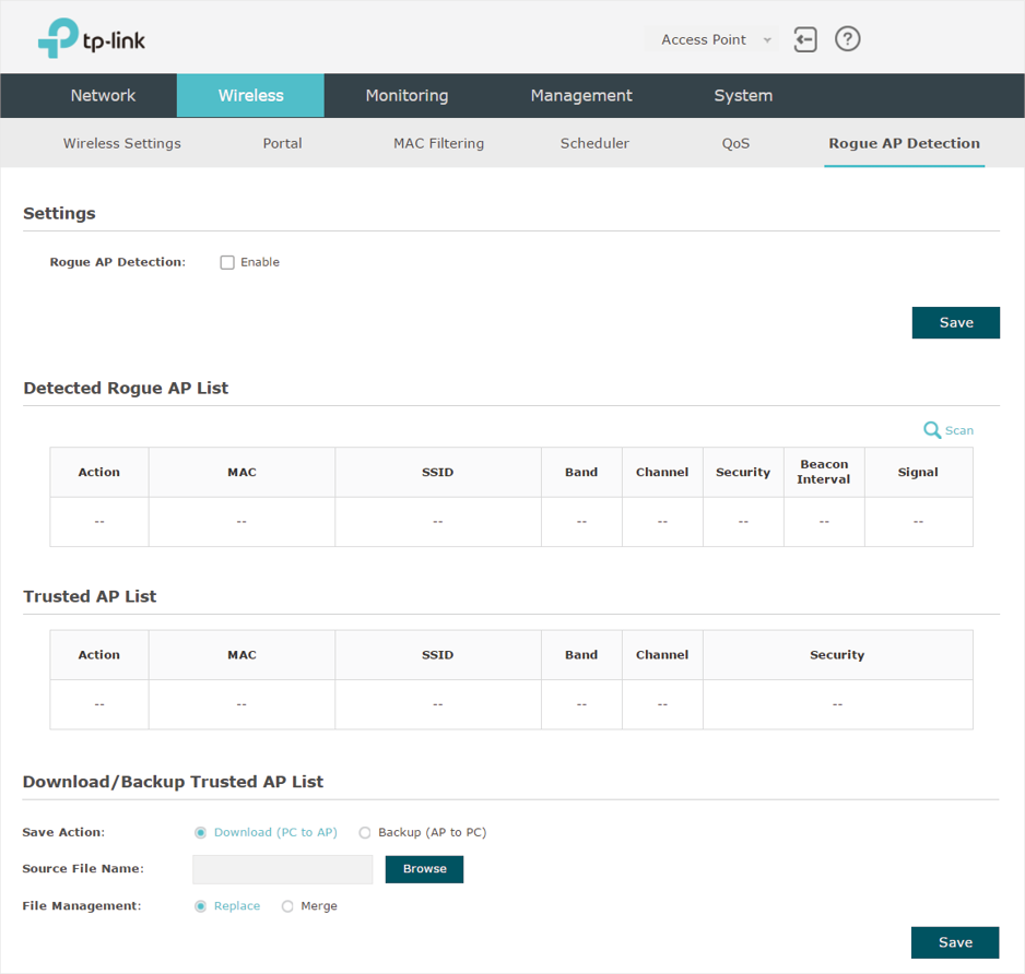
7.1 Detect Rogue APs & Move the Rogue APs to the Trusted AP List
Follow the steps below to detect the nearby APs and move the trusted ones to the Trusted AP list.
1)In the Settings section, check the box to enable Rogue AP Detection. Click Save.
Figure 7-2Enabling Rogue AP Detection

2)In the Detected Rogue AP List section, click  .
.
3)Wait for a few seconds without any operation. After detection is finished, the detected APs will be displayed in the list.
Figure 7-3 Viewing the Detected Rogue APs
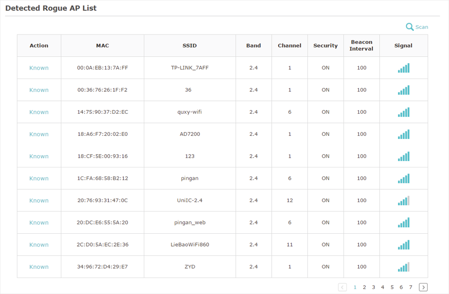
The following table introduces the displayed information of the APs:
|
MAC |
Displays the MAC address of the AP. |
|
SSID |
Displays the SSID of the AP. |
|
Band |
Displays the frequency band the AP is working on. |
|
Channel |
Displays the channel the AP is using. |
|
Security |
Displays whether the security mode is enabled on the AP. |
|
Beacon Interval |
Displays the Beacon Interval value of the EAP. Beacon frames are sent periodically by the AP to announce to the stations the presence of a wireless network. Beacon Interval determines the time interval of the beacon frames sent by the AP device. |
|
Signal |
Displays the signal strength of the AP. |
4)To move the specific AP to the Trusted AP list, click  in the Action column. For example, we move the first two APs in the above Detected Rogue AP list to the Trusted AP list.
5)View the trusted APs in the Trusted AP List section. To move the specific AP back to the Rogue AP list, you can click  in the Action column.
Figure 7-4Viewing Trusted AP List

7.2 Manage the Trusted AP List
You can download the trusted AP list from your local host to the EAP or backup the current Trusted AP list to your local host.
Download the Trusted AP List From the Host
You can import a trusted AP list which records the MAC addresses of the trusted APs. The AP whose MAC address is in the list will not be detected as a rogue AP.
Figure 7-5 Downloading/Backuping Trusted AP List From Host

Follow the steps below to import a trusted AP list to the EAP:
1)Acquire the trusted AP list. There are two ways:
- Backup the list from a EAP. For details, refer to Backup the Trusted AP List to the Host.
- Manually create a trusted AP list. Create a txt. file, input the MAC addresses of the trusted APs in the format XX:XX:XX:XX:XX:XX and use the Space key to separate each MAC address. Save the file as a cfg file.
2)On this page, check the box to choose Download (PC to AP).
3)Click  and select the trusted AP list from your local host.
4)Select the file management mode. Two modes are available: Replace and Merge. Replace means that the current trusted AP list will be replaced by the one you import. Merge means that the APs in the imported list will be added to the current list with the original APs remained.
5)Click Save to import the trusted AP list.
Backup the Trusted AP List to the Host
You can backup the current trusted AP list and save the backup file to the local host.
Figure 7-6 Downloading/Backuping Trusted AP List to Host

Follow the steps below to backup the current trusted AP list:
1)On this page, check the box to choose Backup (AP to PC).
2)Click Save and the current trusted AP list will be downloaded to your local host as a cfg file.

 to select a band and configure the wireless parameters on this band.
 to edit the specific SSID.
